[2024] Diagnosis Page Terminology
Version Details
App
Description: Displays the current app version for troubleshooting.
Notes: Shows the version number in numeric format.
Firmware
Description: Displays the firmware version of the device.
Notes:
- Shows the version when connected.
- Displays empty if not connected.
Hardware Head
Description: Displays the hardware version of the device’s head component.
Notes:
- Shows the version when connected.
- Displays empty if not connected.
Hardware Body
Description: Displays the hardware version of the device’s body component.
Notes:
- Shows the version when connected.
- Displays empty if not connected.
Network Information
The Network module provides details about the network connection status, helping to evaluate connectivity and diagnose issues.
Ping
Used to test the network connection's availability and response time. It also helps evaluate network latency. The response time is displayed in milliseconds (e.g., 200ms).
Heart Beat
Checks the connection status between two devices or servers. Disconnected indicates the connection is not active, while Connected means the connection is normal.
Local Server
Indicates whether the app's local server is connected. A value of 0 means disconnected, and 1 means connected.
PRP (Plan, Recharge, Pause)
Displays the automatic scheduling status to improve efficiency. The status is represented as a numerical array in the format [0,0,0], where the values correspond to plan, recharge, and pause respectively.
Cellular Information
The Cellular module provides information about cellular connectivity, signal strength, and SIM card details to help monitor and diagnose network performance.
Status
Displays the current 4G network status.
- 0: Not connected.
- 1: Connected
RSSI (Received Signal Strength Indicator)
Indicates the received signal strength, commonly used to evaluate cellular signal quality.
- Range: -120 dBm (very weak) to 0 dBm (very strong).
- -1: No data displayed if the device is disconnected.
RSRQ (Reference Signal Received Quality)
Measures signal quality in LTE networks.
- Range: -20 dB (poor) to -3 dB (good).
- -1: No data displayed if the device is disconnected.
CSQ (Signal Quality)
Indicates signal quality in GSM networks.
- Range: 0 to 31 (higher is better).
- 0: No signal or large error.
- -1: No data displayed if the device is disconnected.
Signal
Displays the overall signal strength, including RSSI and other metrics.
- Range: -120 dBm (very weak) to 0 dBm (very strong).
- -1: No data displayed if the device is disconnected.
RSRP (Reference Signal Received Power)
Measures LTE signal power.
- Range: -120 dBm (very weak) to 0 dBm (very strong).
- -1: No data displayed if the device is disconnected.
NetEra
Shows the current network technology code used by the device.
- Values: 2G, 3G, 4G, 5G.
- -1: No data displayed if the device is disconnected.
ICCID (Integrated Circuit Card Identifier)
Displays the unique SIM card identifier for the device.
- Typically 19–20 digits.
- If disconnected, no data is displayed.
ICCID Description
Indicates if the current SIM card is an internal card.
- Displays "CN" for internal cards.
- Displays the ICCID directly for external cards.
RTK Information
 RTK Information
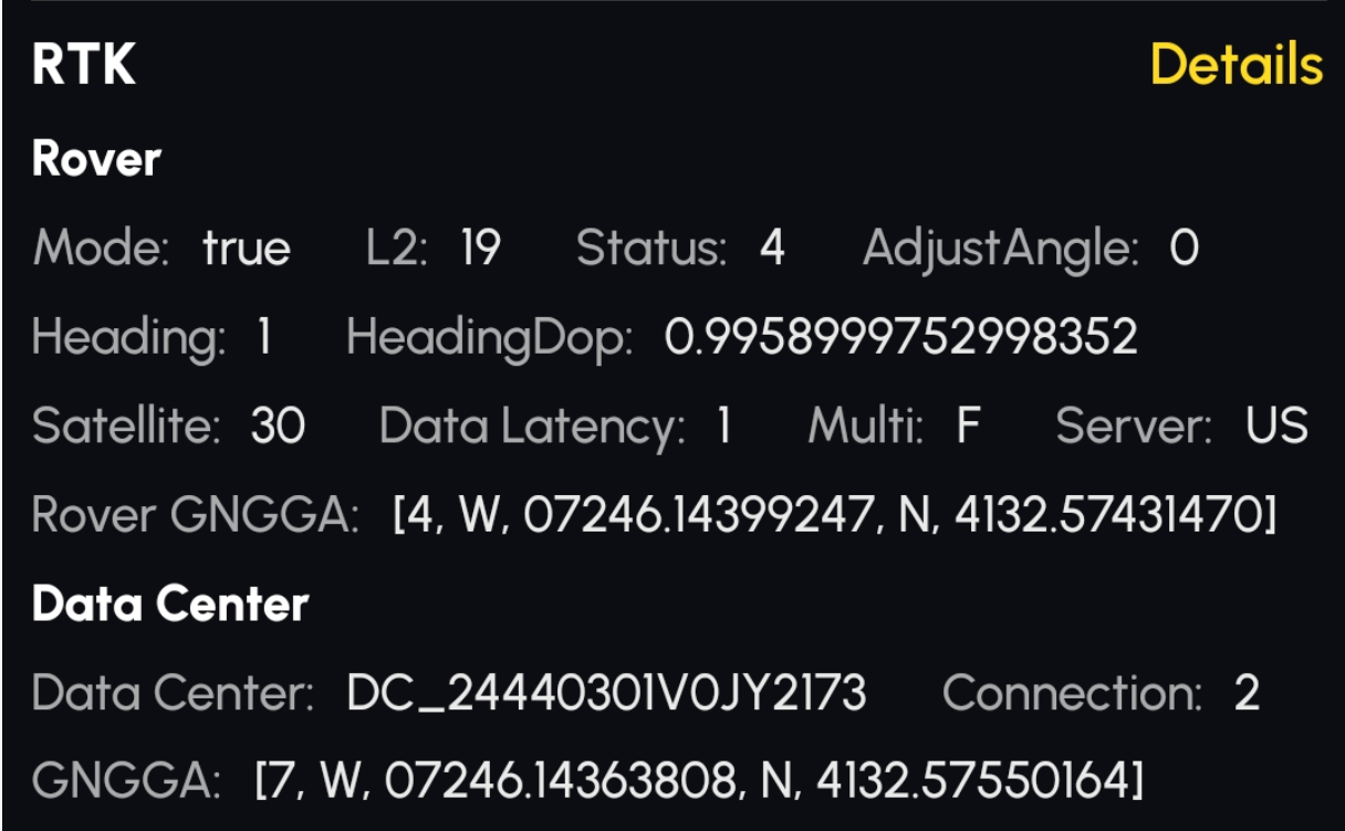
Rover
Refers to the RTK module inside the Yarbo Core.
Mode Base:
Indicates whether the RTK is currently functioning.
- True: RTK is currently functioning
- False: RTK is currently NOT functioning
L2:
Displays the number of satellites detected on the L2 frequency band, based on the right-side antenna.
Note: GNSS satellites use L1, L2, and L5 bands.
- L1: Lowest accuracy, fastest signal.
- L2: Higher accuracy, usually used with L1.
- L5: Highest accuracy, limited coverage.
Status:
Indicates positioning accuracy:
- 1: Single point solution (no RTCM data, meter-level accuracy)
- 2: Pseudorange differential (low RTCM quality, low accuracy)
- 5: Float solution (decimeter to meter-level accuracy)
- 4: Fixed solution (best accuracy)
Note: DC status is either 1 or 7; 7 means DC is properly broadcasting RTCM data.
Adjust Angle:
Indicates initialization success of sensor fusion positioning:
- 0 & 1: Success
- -1: Failure (e.g., RTK≠4 or HeadingDop too high)
- -2: No valid RTK data
Heading:
RTK angle output status:
- -1: No reliable heading
- 1: Reliable heading within ±2°
HeadingDop:
Reliability of the heading value. Lower is better. If >2, the system will rely on IMU instead.
Satellite:
Total number of satellites seen by both the Rover and DC. Based on the left-side antenna.
Data Latency (Age):
Seconds since the last valid RTCM data. >15s may reduce accuracy.
Multi (True/False)
Indicates whether multiple DCs are broadcasting RTCM to the Core.
Server
Shows the server location used for RTK/NTRIP communication (e.g., US).
ROVER GGA: [1/2/5/4, W/E, LON, N/S, LAT]
Rover's real-time location info:
- 1st field: RTK Status
- 2nd & 3rd: Longitude (W/E, LON)
- 4th & 5th: Latitude (N/S, LAT)Format: DDDMM.MMMM (e.g., 07246.1 = 72°46.1′ = 72.7683°). Blank fields may indicate antenna issues.
Data Center Information
The device containing the RTK base module.
DC_SN
Serial number of the Data Center.
Connection (0/1/2/3/4)
Transmission method for RTCM data:
- 0: No data transmission
- 1: LoRa
- 2: NTRIP
- 3: Local HaLow
- 4: Public NTRIP
GNGGA: [1/7, W/E, LON, N/S, LAT]
DC output GPS data:
- 1st: RTK Status (1 or 7; 7 = broadcasting)
- 2nd & 3rd: Longitude
- 4th & 5th: Latitude Blank means DC antenna failure or disconnection.
Status Information
 Status Information
The Status module provides details about the device's operational state and automatic scheduling.
PRP (Plan, Recharge, Pause):
Indicates the status of automatic scheduling for improving efficiency and diagnosing internal scheduling issues.
The status is displayed as a numerical array in the format [0,0,0].The three values correspond to plan, recharge, and pause respectively.
Running:
Displays the current operational status of the device.The specific status codes and details can be found in the below documentation or additional references.
Status Code | Status Explanation |
|---|---|
0 | RunningNormal |
1 | PedestrianAnimalDetect |
2 | RotateHumpDetect |
3 | InStuck |
4 | SerialLoss |
5 | GetAngleError |
6 | WaitForRTK |
7 | WaitForChuteArrive |
8 | CameraError |
9 | HumpAdjustDetect |
10 | HumpFinishBack |
11 | WaitForPushRodArrive |
12 | ChuteOverCurrent |
13 | WaitForRollerArrive |
14 | VisionBypassing |
15 | RunningError |
16 | WaitForBladeArrive |
17 | WaitForBladeSpeed |
18 | CollisionAdjust |
19 | IsDeadendObstacle |
20 | WaitForBladeTemp |
21 | BypassingReturnAction |
22 | NodeError |
23 | WaitForBlowerArrive |
Main Information
The Main module provides details about the machine's operational parameters, including battery, CPU, memory, and motor statuses.
Battery Temp:
Displays the temperature of the battery to check if it is too low or too high.Data shown as a numerical value.
Battery Status:
Shows the current status of the battery.
States include: Charging, Discharging, or Heating.
CPU Usage:
Displays the percentage of CPU currently in use.
- Data shown as a percentage.
- 0: Indicates the device is not connected.
Memory Usage:
Shows the memory utilization percentage to diagnose potential issues.
- Data shown as a percentage.
- 0: Indicates the device is not connected.
Disk Usage:
Displays the disk usage percentage for diagnosing storage-related issues like log file management. Data shown as a percentage.
Left Drive Motor:
Displays the current usage of the left drive motor to evaluate its performance. Data shown as a numerical value.
Right Drive Motor:
Shows the current usage of the right drive motor for performance assessment. Data shown as a numerical value.
Auger:
Displays the current power usage of the auger (snow blower). Data shown as a numerical value.
HaLow Connection Information
The HaLow module provides details about the wireless HaLow connection, including the network name, connection status, and signal strength.
SSID:
Displays the name(SSID) of the Data Center.
Connection:
Shows the current connection status of the HaLow network.
Possible states: true (connected) or false (not connected).
Signal:
Indicates the signal strength of the HaLow connection.
- Data shown as a numerical value.
- Values closer to 0 represent stronger signals.
If the HaLow signal falls to –82 dBm or below, the system will automatically switch to 4G.
-
When operating over 4G, if the HaLow signal rises to –77 dBm or above, it will automatically switch back to HaLow.
Sensor Information
The Sensor module provides data from various sensors, including rain and ultrasonic sensors, to monitor environmental and operational parameters.
Rain Sensor:
- Description: Displays the value from the rain sensor.
- Usage: Indicates the amount of rain detected.
- Notes:
- Values are shown as numbers.
- Threshold: 1500.
- The more rain detected, the better the conductivity (lower resistance), resulting in smaller values.
Front Ultrasonic Sensor:
- Description: Displays the values from the front ultrasonic sensors.
- Usage: Used for distance measurement or obstacle detection.
- Notes: Values are shown as numbers.
Camera Information
The Camera module provides details about the camera's version, status, and MAC address for all camera modules (LC: Left Camera, RC: Right Camera, FC: Front Camera, BC: Back Camera).
Version:
- Description: Displays the version number of the camera firmware.
- Usage: Used to verify the camera's firmware version.
- Notes: Shown as a numerical value (e.g., V1.0.0).
State:
Description: Displays the current state of the camera.
Usage: Helps determine the operational status of the camera.
Notes:
- 0: Normal operation.
- 1: Disabled.
- 2: Camera disconnected.
- 3: Camera ping failed.
Additional explanation:
- If ping fails, it indicates the camera module is not reachable.
- Disconnection may occur after initial proper operation.
MAC Address:
Displays the MAC address of the camera.
Related Articles
[2024] Instruction of Setting Page of Yarbo APP
The Yarbo Settings Page provides you with complete control over all the essential aspects of your Yarbo device, allowing you to make adjustments, update settings, and access valuable information. This guide will take you through each feature of the ...[2024] Instructions on Route Related Settings on the Area Settings Page
Title: How to Get Your Satisfied Mowing Route? Instructions on Route Related Settings on the Area Settings Page Are you looking for the perfect mowing route for your lawn? Configuring the ideal mowing pattern and route can significantly improve both ...[2024] Yarbo App: New App Page (Yarbo Snow Blower)
[2024] What Would Cause Yarbo to Lose GPS Signals?
Maintaining a stable GPS signal is essential for Yarbo to function efficiently. While Yarbo’s advanced system ensures smooth operation, several factors can affect its GPS performance. This guide covers common causes of GPS signal loss and how to ...[2024] Create Work Plan through APP
Creating a work plan is a key feature of the Yarbo app that allows you to customize and automate your lawn care. Here’s a step-by-step guide to help you set up your first work plan: Enter My Yard Tap on the “Enter My Yard” button. This will bring you ...